KoreaDevKNOWLEDGE SHARING

Content typeLearn

AI INFRASTRUCTURE · 01 / 12

The big picture of AI data centers

Covers how the rack, power, cooling, servers, network, storage, GPUs, and AI service connect into a single failure domain.

Difficulty
Intermediate
Structure
Core units 4 · Judgment activities · Three-stage assessment

NEW HIRE ONBOARDING

Start in the order you would receive your first assignment

So that even a new hire with no prior IT background can follow along, we start with the situation, the task, the evidence, and when to report, before difficult definitions.

  1. 01

    Read the situation in one sentence

    Instead of memorizing rack numbers and equipment names, use evidence to map the dependencies from a service request down to the facility, along with the common points of failure.

  2. 02

    Today's assignment

    Document the stop conditions and recovery evidence for the full path to the service in a work record.

  3. 03

    Evidence that shows the work is complete

    Reviewed against official documentation and training output. Commands and performance tests on real hardware are unconfirmed.

  4. 04

    When to stop and ask a senior colleague

    The current on PDU A in rack A reached the warning line, but the GPU nodes are healthy. Which action is correct?

Unpack unfamiliar terms first

Work permit
An approval record that confirms the target, scope, time, owner, and stop authority for the work.

Operational question for this course

How far does one server's failure spread across the power, cooling, and network boundaries?

Instead of memorizing rack numbers and equipment names, use evidence to map the dependencies from a service request down to the facility, along with the common points of failure.

CORE UNIT 1 / 4

Server rooms and work safety

Judge the facility boundary and the safety conditions that must hold before work starts.

Difficulty
Intermediate
Structure
Lessons 5 · Labs 2 · Assessment

Diagrams and tables: composed by the author using each lesson's official primary sources. Find the originals and review dates at the end of that lesson.

PREREQUISITE CHECK

Three things to check before reading

This is not a test of memorized answers. Think about each question first, then open the explanation to review the foundational concepts used in this course.

1Does this unit send commands to real equipment?

No. Read the training output in the browser and make the judgment there. Any separate reproduction is done only in an approved isolated environment.

2What permissions and environment must you confirm before the lab?

No facility changes · read-only BMC account. Documentation management network 192.0.2.0/24.

3How do you record a value you have never seen before and a test you have not yet run?

Record it as unconfirmed. Distinguish expected training output from actual measurements, and do not fill in blanks with unapproved work.

TEXTBOOK GUIDE

Main text that covers each concept from its background to the criteria for judging it

We explain the material section by section so readers new to IT can connect causes and effects without memorizing terms.

  1. Explain the components and failure boundaries of server rooms and work safety using a diagram.
  2. Judge the state of server rooms and work safety from command output and observed values.
  3. Document the stop conditions and recovery evidence for server rooms and work safety in a work record.
Server rooms and work safety Lab environment and safety boundaries
HardwareRack diagram · PDU A/B · BMC sensor fixture
SoftwareUbuntu 24.04 LTS·ipmitool 1.8.x
Required permissionsNo facility changes · read-only BMC account
NetworkingDocumentation-range management network 192.0.2.0/24

Reviewed against official documentation and training output. Commands and performance tests on real hardware are unconfirmed.

Applies to version: Ubuntu Server 24.04 LTS · ipmitool 1.8.x · Manuscript review date: 2026-09-01

CONCEPT FLOW

How the chapters connect

The chapters are not isolated short answers to memorize. Follow them from left to right to see how each chapter's concepts support the next decision.

  1. 1.Start the checks at the work permit
  2. 2.Fix the lab target for the on-site comparison
  3. 3.Distinguish the output of the hazard review from what it means
  4. 4.Decide whether to proceed or stop at the observation record
  5. 5.Re-verify recovery for server rooms and work safety
Server rooms and work safety: the overall map. If you lose track while reading the detailed explanations and chapters below, return to this sequence.

CONTROLLED EXPLANATION

Follow the evidence to check, one step at a time

Current explanation · 1/5 · Start the checks at the work permit

Up next: Fix the lab target for the on-site comparison

  1. Start the checks at the work permit

    Do not guess the cause and start by changing settings. If you group the following evidence into records from the same time window, another operator can reproduce the boundary at which the expected state broke.

  2. Fix the lab target for the on-site comparison

    Lab scenario:: Compare the fixture's work order with the BMC sensor list and write a Go/No-Go record for entering the site. Instructions:: In the browser, read the training output below and write a verdict. Do not send the commands to real equipment. To reproduce the commands separately, prepare an approved isolated environment with the relevant tools and example files. Save the entire output, and if the permit, the labeling, and the actual asset do not match, do not move on to the next change.

  3. Distinguish the output of the hazard review from what it means

    The point is not to memorize the values themselves but to confirm that the sensors can be read and that the temperatures and PSU status belong to the target named in the work order. The values shown are reproduced examples for training, not measurements taken on real equipment. Identifiers and values can differ by device, driver, and cluster.

  4. Decide whether to proceed or stop at the observation record

    You succeed when a single pre-check sheet explains the permit number, the rack and asset match, the emergency procedure, the sensor state, and whether to stop. Record the execution time, target identity, commands used, key output, verdict, and next action together in the result.

  5. Re-verify recovery for server rooms and work safety

    If the target or the labeling differs, do not touch anything on site; record photos, the asset tag and the time. Keep the No-Go until the work order is corrected or the approver re-confirms the target. After recovery, measure again with the same commands and the same success criteria. Do not close an incident just because things appear normal.

Conceptual explanation 01

Facility work begins only after the permit and the hazard review

Work permit: an approval record that confirms the target, scope, time, owner, and stop authority for the work.

Work in a server room deals with energy and access boundaries before technical commands. Electricity, weight, hot exhaust air, rotating parts and noise are hazards that no software rollback can undo.

Observation can begin only after the work permit, a companion, the location of the emergency shutoff, appropriate protective equipment, and the authority to stop work are in place. The lab in this unit is limited to reading approval information and BMC sensors, without operating any facility equipment.

Even when a server looks powered off, voltage can remain in the PDU and PSU, and rack rails and equipment weight create separate mechanical hazards. Do not read the power state on a screen as evidence of zero voltage.

In the training example the work order specified U18 in rack 07 but the on-site equipment was in U20. Even if the two devices look identical, that is no basis for saying the target is the same. Pulling a cable because the power indicator on U18 is off can affect other work. First reconcile the asset tag with the approved target, and stop everything except observation until the discrepancy is resolved.
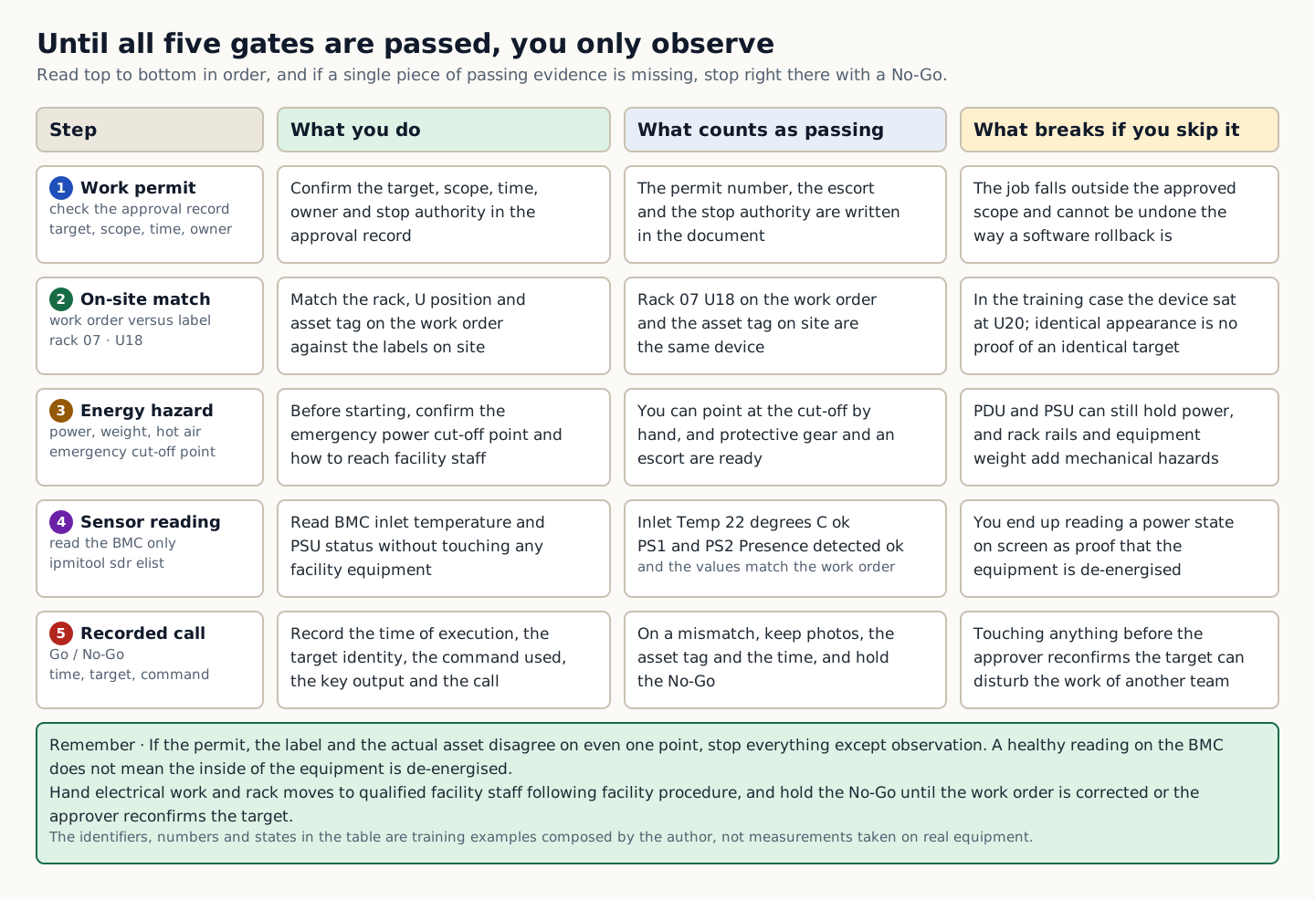
A pre-check table giving, for each of five steps (work permit, on-site match, energy hazard, sensor observation, and verdict record), what to do, what to look for to pass, and what breaks if the step is skipped
How to read the figure Facility work starts only after the permit and hazard check. Read the table from top to bottom in order of badges 1 to 5, and within each row look at what is done, what counts as a pass, and what breaks if the step is skipped. The steps are work permit, on-site verification, energy hazards, sensor observation, and verdict record, and the left cell also lists the values handled at that step. Passing evidence must be confirmed both in the documents and on site, as with rack 07 U18 in row 2 and the emergency shutoff location in row 3. In row 4, Inlet Temp 22 degrees C ok and PS1 · PS2 Presence detected ok mean only that the sensors can be read and the values match the target in the work order, not that the inside of the equipment is de-energized. If even one row lacks passing evidence, stop there with a No-Go and take no action other than observation. The green box at the bottom holds the decision rules, and electrical work and rack moves are handed over to qualified staff following facility procedures. The identifiers, numbers, and states in the table are training examples composed by the author, and the figure does not depict all physical cabling or time proportions. Source: composed by the author based on NVIDIA DCGM User Guide · OSHA Electrical Safety.
Why does this happen?
Observation can begin only after the work permit, a companion, the location of the emergency shutoff, appropriate protective equipment, and the authority to stop work are in place. The lab in this unit is limited to reading approval information and BMC sensors, without operating any facility equipment.
When is it a problem?
If you see a mismatch between the permit, the label, and the actual asset, there are insufficient grounds to proceed.
Common beginner misconceptions
A normal status on the BMC does not mean the equipment is de-energized inside. Leave electrical work and rack moves to qualified staff following facility procedures.
How to verify it yourself
Compare the rack, U position, and asset tag on the work order against the labels on site. Confirm the emergency power shutoff location and the contact path to the facilities owner before starting work.
To summarize this sectionYou succeed when a single pre-check sheet explains the permit number, the rack and asset match, the emergency procedure, the sensor state, and whether to stop.

CHAPTER 1 / 5

Start the checks at the work permit

Do not guess the cause and start by changing settings. If you group the following evidence into records from the same time window, another operator can reproduce the boundary at which the expected state broke.

1. Compare the rack, U position, and asset tag in the work order against the on-site labels. 2. Before starting work, confirm the location of the emergency power cutoff and how to reach the facility staff. 3. Read the BMC inlet temperature and the PSU status, but do not operate facility equipment directly. 4. When an operation is required, reconfirm the authorization and escort requirements.

CHAPTER 2 / 5

Fix the lab target for the on-site comparison

Commands for reproducing the isolated environment · do not run them in the browser
ipmitool -I lanplus -H 192.0.2.21 -U observer sdr elist
# enter the password through a secure prompt; never place it on the command line

CHAPTER 3 / 5

Distinguish the output of the hazard review from what it means

Expected output for training · not an actual measurement
Inlet Temp       | 22 degrees C      | ok
PS1 Status       | Presence detected | ok
PS2 Status       | Presence detected | ok

CHAPTER 4 / 5

Decide whether to proceed or stop at the observation record

CHAPTER 5 / 5

Re-verify recovery for server rooms and work safety

CONCRETE CASES

Compare the fixture's work order with the BMC sensor list and write a Go/No-Go record for entering the site.

Even when a server looks powered off, voltage can remain in the PDU and PSU, and rack rails and equipment weight create separate mechanical hazards. Do not read the power state on a screen as evidence of zero voltage.

Wrong responses and boundaries to check

A normal status on the BMC does not mean the equipment is de-energized inside. Leave electrical work and rack moves to qualified staff following facility procedures.

If the target or the labeling differs, do not touch anything on site; record photos, the asset tag and the time. Keep the No-Go until the work order is corrected or the approver re-confirms the target. After recovery, measure again with the same commands and the same success criteria. Do not close an incident just because things appear normal.

INTERACTIVE LAB 1 / 2

Lab 1 · Find the basis for a verdict in the output

Enter values in the browser and check the execution results and the failure and recovery paths. No commands are ever sent to real equipment or the NAS.

Lab scenario:: Compare the fixture's work order with the BMC sensor list and write a Go/No-Go record for entering the site. Instructions:: In the browser, read the training output below and write a verdict. Do not send the commands to real equipment. To reproduce the commands separately, prepare an approved isolated environment with the relevant tools and example files. Save the entire output, and if the permit, the labeling, and the actual asset do not match, do not move on to the next change.

Inlet Temp       | 22 degrees C      | ok
PS1 Status       | Presence detected | ok
PS2 Status       | Presence detected | ok

The point is not to memorize the values themselves but to confirm that the sensors can be read and that the temperatures and PSU status belong to the target named in the work order. The values shown are reproduced examples for training, not measurements taken on real equipment. Identifiers and values can differ by device, driver, and cluster.

INTERACTIVE LAB 2 / 2

Lab 2 · Plan for stopping and recovery

Enter values in the browser and check the execution results and the failure and recovery paths. No commands are ever sent to real equipment or the NAS.

A normal status on the BMC does not mean the equipment is de-energized inside. Leave electrical work and rack moves to qualified staff following facility procedures.

KEY TERMS

Key terms in this unit

Work permit
An approval record that confirms the target, scope, time, owner, and stop authority for the work.

UNIT WORKBOOK

Exercises and worksheets for applying concepts to new situations

Start by checking basic principles, then expand to practical workplace decisions. After submitting an answer, you can see why every option is correct or incorrect, not just the correct answer.

Document the stop conditions and recovery evidence for server rooms and work safety in a work record.

PERSONAL WORKSHEET

A learning worksheet you adapt to your own environment

Your input remains only on the current browser screen and is not stored or transmitted externally. Use categories and pseudonyms instead of actual sensitive information.

OFFICIAL SOURCES

Verify against official sources

Reviewed against official documentation and training output. Commands and performance tests on real hardware are unconfirmed.

CORE UNIT 2 / 4

Racks and server components

Links racks, power, and server parts to asset identity.

Difficulty
Intermediate
Structure
Lessons 5 · Labs 2 · Assessment

Diagrams and tables: composed by the author using each lesson's official primary sources. Find the originals and review dates at the end of that lesson.

PREREQUISITE CHECK

Three things to check before reading

This is not a test of memorized answers. Think about each question first, then open the explanation to review the foundational concepts used in this course.

1Does this unit send commands to real equipment?

No. Read the training output in the browser and make the judgment there. Any separate reproduction is done only in an approved isolated environment.

2What permissions and environment must you confirm before the lab?

No facility changes · read-only BMC account. Documentation management network 192.0.2.0/24.

3What evidence did you record in the previous unit, "Server rooms and work safety"?

You succeed when a single pre-check sheet explains the permit number, the rack and asset match, the emergency procedure, the sensor state, and whether to stop.

TEXTBOOK GUIDE

Main text that covers each concept from its background to the criteria for judging it

We explain the material section by section so readers new to IT can connect causes and effects without memorizing terms.

  1. Explain the components and failure boundaries of racks and server components using a diagram.
  2. Judge the state of racks and server components from command output and observed values.
  3. Document the stop conditions and recovery evidence for racks and server components in a work record.
Racks and server components Lab environment and safety boundaries
HardwareRack diagram · PDU A/B · BMC sensor fixture
SoftwareUbuntu 24.04 LTS·ipmitool 1.8.x
Required permissionsNo facility changes · read-only BMC account
NetworkingDocumentation-range management network 192.0.2.0/24

Reviewed against official documentation and training output. Commands and performance tests on real hardware are unconfirmed.

Applies to version: Ubuntu Server 24.04 LTS · ipmitool 1.8.x · Manuscript review date: 2026-09-01

CONCEPT FLOW

How the chapters connect

The chapters are not isolated short answers to memorize. Follow them from left to right to see how each chapter's concepts support the next decision.

  1. 1.Start the check at the rack position
  2. 2.Fix the lab target for the chassis
  3. 3.Distinguish the output of the parts list from its meaning
  4. 4.Make the go/stop decision on CMDB linkage
  5. 5.Re-verify recovery for racks and server components
Racks and server components: the overall map. If you lose track while reading the detailed explanations and chapters below, return to this sequence.

CONTROLLED EXPLANATION

Follow the evidence to check, one step at a time

Current explanation · 1/5 · Start the check at the rack position

Up next: Fix the lab target for the chassis

  1. Start the check at the rack position

    Do not guess the cause and start by changing settings. If you group the following evidence into records from the same time window, another operator can reproduce the boundary at which the expected state broke.

  2. Fix the lab target for the chassis

    Lab scenario:: From a server inventory fixture, extract the physical, firmware, and OS identifiers and merge them into a single asset record. Instructions:: In the browser, read the training output below and write a verdict. Do not send the commands to real equipment. To reproduce the commands separately, prepare an approved isolated environment with the relevant tools and example files. Save the entire output, and if even one of the serial, MAC, or intended use does not match, do not move on to the next change.

  3. Distinguish the output of the parts list from its meaning

    The point is not to memorize the values themselves but to confirm that the identifiers from the three layers converge on the single asset in the work order. The values shown are reproduced examples for training, not measurements taken on real equipment. Identifiers and values can differ by device, driver, and cluster.

  4. Make the go/stop decision on CMDB linkage

    Success means linking the rack position, chassis serial, GPU and NIC PCI addresses, disk serials, and owner with nothing missing, and flagging every mismatch. Record the execution time, target identity, commands used, key output, verdict, and next action together in the result.

  5. Re-verify recovery for racks and server components

    If there is a mismatch, do not start a firmware update or an OS installation. Attach the read-only inventory and ask the asset owner to correct the CMDB or the work target. After recovery, measure again with the same commands and the same success criteria. Do not close an incident just because things appear normal.

Conceptual explanation 01

Link identity from the rack position through to the operational asset

Identity: information such as a serial number or asset tag that ties physical equipment and operational records to the same object.

The U position in the rack, the chassis serial, the BMC name, the NIC MAC, and the disk serial are identities that refer to the same physical device from different layers. If you record only one of these aliases, targets get mixed up during replacement and failure analysis.

The acceptance record starts from the rack position and works down to the chassis, motherboard, CPU and memory, PCIe devices, NIC, disks, and PSU. Each identifier must be linked to a CMDB entry so that a logical node name can be traced to the actual parts.

When a GPU is not visible to the OS, each case needs a different recovery: the device is physically absent, the PCIe link is down, or the driver failed to bind. That is why physical inventory and OS inventory are collected at the same moment.

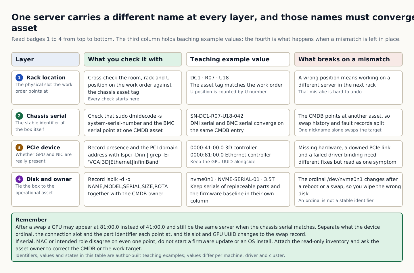
In the training example the GPU was at PCI address 41:00.0 before replacement but appeared at 81:00.0 afterwards. You must not conclude it is a different server from the address change alone. Confirm that the chassis serial is the same, then link the slot and GPU UUID changes to the replacement record. You must distinguish what the device enumeration order, the connection position and the part's own identifier each refer to.

A cross-check table that splits four layers (rack location, chassis serial, PCIe device, and disk and owner) into how to check them, teaching example values, and what breaks on a mismatch
How to read the figure Read badges 1 to 4 on the left from top to bottom; each row is a name from a different layer that refers to the same server. The second column is how that name is verified, the third holds training example values, and the fourth is the consequence of leaving a mismatch unresolved. DC1 · R07 · U18, SN-DC1-R07-U18-042, 0000:41:00.0, 0000:81:00.0, and nvme0n1 · NVME-SERIAL-01 · 3.5T in the table are training example values composed by the author and vary by hardware, driver, and cluster. Row 3 highlights that missing hardware, a PCIe link that is down, and a failed driver binding require different recoveries but can look like a single symptom. The green summary box at the bottom is the decision rule: even if a GPU address changes from 41:00.0 to 81:00.0 after a replacement, it is the same server if the chassis serial matches, and if any of the serial, MAC, or intended role does not match, do not start a firmware update or OS installation. The table shows the order in which identities are linked; it does not depict the actual rack layout or physical cabling. Source: composed by the author based on Linux PCI Support Library · NVIDIA DCGM User Guide.
Why does this happen?
The acceptance record starts from the rack position and works down to the chassis, motherboard, CPU and memory, PCIe devices, NIC, disks, and PSU. Each identifier must be linked to a CMDB entry so that a logical node name can be traced to the actual parts.
When is it a problem?
If even one of the serial, MAC, or intended use does not match, there are insufficient grounds to proceed.
Common beginner misconceptions
Sequence numbers such as device 0 or /dev/nvme0n1 can change after a reboot or replacement. Match devices by serial number and UUID, and also record the PCI address as location information for the current slot and topology. Do not use the PCI address alone as a permanent device identifier.
How to verify it yourself
Check the room, rack, and U position on the work order and the chassis asset tag. Confirm that the DMI serial and the BMC serial point to the same asset in the CMDB.
To summarize this sectionYou succeed when you link the rack position, chassis serial, GPU/NIC PCI addresses, disk serials, and owner with nothing missing, and flag any mismatches.

CHAPTER 1 / 5

Start the check at the rack position

Do not guess the cause and start by changing settings. If you group the following evidence into records from the same time window, another operator can reproduce the boundary at which the expected state broke.

1. Verify the room, rack, and U position in the work order and the chassis asset tag. 2. Check whether the DMI serial and the BMC serial point to the same asset in the CMDB. 3. Use lspci and lsblk to record that the GPU, NIC, and storage are actually present. 4. Keep the serial and firmware baseline of replaceable parts in a separate column.

CHAPTER 2 / 5

Fix the lab target for the chassis

Commands for reproducing the isolated environment · do not run them in the browser
sudo dmidecode -s system-serial-number
lspci -Dnn | grep -Ei 'VGA|3D|Ethernet|InfiniBand'
lsblk -d -o NAME,MODEL,SERIAL,SIZE,ROTA

CHAPTER 3 / 5

Distinguish the output of the parts list from its meaning

Expected output for training · not an actual measurement
SN-DC1-R07-U18-042
0000:41:00.0 3D controller: NVIDIA Corporation Device ...
0000:81:00.0 Ethernet controller: Mellanox Technologies ...
nvme0n1  NVMe_Model  NVME-SERIAL-01  3.5T  0

CHAPTER 4 / 5

Make the go/stop decision on CMDB linkage

CHAPTER 5 / 5

Re-verify recovery for racks and server components

CONCRETE CASES

From a server inventory fixture, extract the physical, firmware and OS identifiers and merge them into a single asset record.

When a GPU is not visible to the OS, each case needs a different recovery: the device is physically absent, the PCIe link is down, or the driver failed to bind. That is why physical inventory and OS inventory are collected at the same moment.

Wrong responses and boundaries to check

Sequence numbers such as device 0 or /dev/nvme0n1 can change after a reboot or replacement. Match devices by serial number and UUID, and also record the PCI address as location information for the current slot and topology. Do not use the PCI address alone as a permanent device identifier.

If there is a mismatch, do not start a firmware update or an OS installation. Attach the read-only inventory and ask the asset owner to correct the CMDB or the work target. After recovery, measure again with the same commands and the same success criteria. Do not close an incident just because things appear normal.

INTERACTIVE LAB 1 / 2

Lab 1 · Find the basis for a verdict in the output

Enter values in the browser and check the execution results and the failure and recovery paths. No commands are ever sent to real equipment or the NAS.

Lab scenario:: From a server inventory fixture, extract the physical, firmware, and OS identifiers and merge them into a single asset record. Instructions:: In the browser, read the training output below and write a verdict. Do not send the commands to real equipment. To reproduce the commands separately, prepare an approved isolated environment with the relevant tools and example files. Save the entire output, and if even one of the serial, MAC, or intended use does not match, do not move on to the next change.

SN-DC1-R07-U18-042
0000:41:00.0 3D controller: NVIDIA Corporation Device ...
0000:81:00.0 Ethernet controller: Mellanox Technologies ...
nvme0n1  NVMe_Model  NVME-SERIAL-01  3.5T  0

The point is not to memorize the values themselves but to confirm that the identifiers from the three layers converge on the single asset in the work order. The values shown are reproduced examples for training, not measurements taken on real equipment. Identifiers and values can differ by device, driver, and cluster.

INTERACTIVE LAB 2 / 2

Lab 2 · Plan for stopping and recovery

Enter values in the browser and check the execution results and the failure and recovery paths. No commands are ever sent to real equipment or the NAS.

Sequence numbers such as device 0 or /dev/nvme0n1 can change after a reboot or replacement. Match devices by serial number and UUID, and also record the PCI address as location information for the current slot and topology. Do not use the PCI address alone as a permanent device identifier.

KEY TERMS

Key terms in this unit

Identity
Information, such as serial numbers and asset tags, that links physical equipment and operational records to the same target.

UNIT WORKBOOK

Exercises and worksheets for applying concepts to new situations

Start by checking basic principles, then expand to practical workplace decisions. After submitting an answer, you can see why every option is correct or incorrect, not just the correct answer.

Document the stop conditions and recovery evidence for racks and server components in a work record.

PERSONAL WORKSHEET

A learning worksheet you adapt to your own environment

Your input remains only on the current browser screen and is not stored or transmitted externally. Use categories and pseudonyms instead of actual sensitive information.

OFFICIAL SOURCES

Verify against official sources

Reviewed against official documentation and training output. Commands and performance tests on real hardware are unconfirmed.

CORE UNIT 3 / 4

Power and cooling

Explain how power path and cooling failures propagate to GPU workloads.

Difficulty
Intermediate
Structure
Lessons 14 · Labs 2 · Assessment

Diagrams and tables: composed by the author using each lesson's official primary sources. Find the originals and review dates at the end of that lesson.

PREREQUISITE CHECK

Three things to check before reading

This is not a test of memorized answers. Think about each question first, then open the explanation to review the foundational concepts used in this course.

1Does this unit send commands to real equipment?

No. Read the training output in the browser and make the judgment there. Any separate reproduction is done only in an approved isolated environment.

2What permissions and environment must you confirm before the lab?

No facility changes · read-only BMC account. Documentation management network 192.0.2.0/24.

3What evidence did you record in the previous unit, "Racks and server components"?

Success means linking the rack position, chassis serial, GPU and NIC PCI addresses, disk serials, and owner with nothing missing, and flagging every mismatch.

TEXTBOOK GUIDE

Main text that covers each concept from its background to the criteria for judging it

We explain the material section by section so readers new to IT can connect causes and effects without memorizing terms.

  1. Explain the components and failure boundaries of power and cooling using a diagram.
  2. Judge the state of power and cooling from command output and observed values.
  3. Document the stop conditions and recovery evidence for power and cooling in a work record.
Power and cooling Lab environment and safety boundaries
HardwareRack diagram · PDU A/B · BMC sensor fixture
SoftwareUbuntu 24.04 LTS·ipmitool 1.8.x
Required permissionsNo facility changes · read-only BMC account
NetworkingDocumentation-range management network 192.0.2.0/24

Reviewed against official documentation and training output. Commands and performance tests on real hardware are unconfirmed.

Applies to version: Ubuntu Server 24.04 LTS · ipmitool 1.8.x · Manuscript review date: 2026-09-01

CONCEPT FLOW

How the chapters connect

The chapters are not isolated short answers to memorize. Follow them from left to right to see how each chapter's concepts support the next decision.

  1. 1.Start the checks at the power input
  2. 2.Fix the lab target for server load
  3. 3.Distinguish the output of heat rejection from what it means
  4. 4.Make the go/stop decision on the performance results
  5. 5.Re-verify recovery of power and cooling
  6. 6.An In-Rack CDU's loop ends inside the rack
  7. 7.An In-Row CDU serves the whole row as a single loop
  8. 8.Compare the two structures on the same items
  9. 9.kW figures without an approach temperature cannot be compared
  10. 10.CDU vendor review: what the official material confirms
  11. 11.Criteria for choosing by site conditions
  12. 12.Fix the order of checks
  13. 13.A lab in reading candidate specifications under the same conditions
  14. 14.Hold the placement decision if the specification or redundancy is lacking
Power and cooling: the overall map. If you lose track while reading the detailed explanations and chapters below, return to this sequence.

CONTROLLED EXPLANATION

Follow the evidence to check, one step at a time

Current explanation · 1/14 · Start the checks at the power input

Up next: Fix the lab target for server load

  1. Start the checks at the power input

    Do not guess the cause and start by changing settings. If you group the following evidence into records from the same time window, another operator can reproduce the boundary at which the expected state broke.

  2. Fix the lab target for server load

    Lab scenario:: Using the provided sensor snapshot, judge the power headroom and the effect of the cooling anomaly on the GPU clock. Instructions:: In the browser, read the training output below and write a verdict. Do not send the commands to real equipment. To reproduce the commands separately, prepare an approved isolated environment with the relevant tools and example files. Save the entire output, and if you see loss of an A/B feed, a temperature rise, or throttling, do not move on to the next change.

  3. Distinguish the output of heat rejection from what it means

    The point is not to memorize the values themselves but to confirm that power, temperature, and clock are within the allowed range at the same moment and that no throttle reason is present. The values shown are reproduced examples for training, not measurements taken on real equipment. Identifiers and values can differ by device, driver, and cluster.

  4. Make the go/stop decision on the performance results

    You succeed when you state in numbers the headroom on each A/B feed, the temperature change, the clock impact, and the threshold for stopping new load. Record the execution time, target identity, commands used, key output, verdict, and next action together in the result.

  5. Re-verify recovery of power and cooling

    If the temperature keeps rising or one feed disappears, stop new workloads and reduce the load. Check the PDU and CRAC status with the facilities owner, then re-verify under the same load. After recovery, measure again with the same commands and the same success criteria. Do not close an incident just because things appear normal.

  6. An In-Rack CDU's loop ends inside the rack

    In this example, the In-Rack CDU fits into a 4U slot at the top or bottom of a 19-inch rack. Facility water enters the primary side of that 4U unit, takes heat from the equipment coolant in a plate heat exchanger, and returns. On the secondary side, equipment coolant passes through the rack manifold and the cold plates in each tray and returns within the same rack. Because the loop is short, the fluid volume is small, and filling, draining, and sampling are easy.

  7. An In-Row CDU serves the whole row as a single loop

    An In-Row CDU is a floor-standing cabinet the same height as a rack, placed at the end of a row, between rows, or in an aisle. Facility water comes only as far as this cabinet, and the secondary-side equipment coolant supply header runs above the row or under the floor past every rack before returning through the return header. Because one unit serves the whole row, there are only one or two units to manage and no rack space is used, but the headers, branches, and hoses form one large loop with a volume of hundreds of liters or more.

  8. Compare the two structures on the same items

    Form factor and location:: In-Rack units are built into a 4U slot at the top or bottom of the rack; In-Row units are floor-standing cabinets as tall as the racks, placed at the end of a row, between rows, or in an aisle. Scope of one unit:: In-Rack serves one rack; In-Row serves anywhere from several racks to an entire row. At the 2 MW class, official material includes an example of one unit serving 12 GB300 NVL72 racks. Where facility water reaches:: With In-Rack, facility water enters the rack itself, so facility water piping runs inside the IT room; with In-Row, it reaches only the CDU, so only equipment coolant piping runs along the rack row. Technology cooling volume:: In-Rack holds a few tens of liters (for example, 15.6 L), which makes filling, draining, and sampling easy; In-Row puts all headers, branches, and hoses on one loop, reaching hundreds of liters or more. Impact when one CDU fails:: With In-Rack, only that one rack; with In-Row, every rack the CDU serves, so add CDU N+1 or a UPS as well. What needs maintenance and water quality management:: In-Rack means managing filters, pumps, and sampling on one CDU per rack; In-Row means one or two CDUs per row. Rack space:: With In-Rack, the CDU occupies 4U, reducing the number of trays; with In-Row, the rack is unaffected, but floor space and front and rear service aisles are required. Where each fits:: In-Rack suits a small number of racks, retrofits into rooms that remain partly air-cooled, and rapid rack-by-rack growth; In-Row suits new builds and large AI clusters where high-density racks arrive a full row at a time.

  9. kW figures without an approach temperature cannot be compared

    A heat exchanger cannot make the two water temperatures exactly equal. That gap between the facility water supply temperature and the technology cooling supply temperature is the approach temperature; the smaller it is, the colder the coolant you can produce from the same facility water, and conversely the same coolant temperature can be produced from warmer facility water, which reduces the chiller load. That is why vendor datasheets always attach a condition, such as "○○ kW at ○ °C ATD".

  10. CDU vendor review: what the official material confirms

    Vertiv:: The In-Rack CoolChip CDU 121 (4U, 121 kW at 4 °C ATD, dual pumps, 50 µm filter), the In-Row and perimeter CoolChip CDU 600, 1350, and 2300 (600, 1,350, and 2,300 kW at 4 °C ATD, liquid-to-liquid), and the liquid-to-air CoolChip CDU 70 (70 kW) form one product family, and Vertiv's own technical documents summarize the pros and cons of In-Rack (1 rack affected), In-Row (several racks), and gallery (several rows). CoolIT Systems:: The range includes the In-Rack CHx80 (4U, 80 kW, N+1 pumps and power) and CHx200, plus the Row-based CHx2000 (2,000 kW at 5 °C ATD, 2,125 LPM at 35 psi, front and rear service, 12 racks of GB300 NVL72 per CDU). Capacity figures are stated together with ATD, flow rate, and pressure. Motivair by Schneider Electric:: The In-Rack CDU (4U, up to 105 kW, dual circulation pumps, mounted at the top or bottom of the rack) and the floor-standing MCDU-25 to MCDU-60 form one portfolio, and the MCDU-45 and 55 for utility corridor installation were announced on 2025-12-15. Since the 2025 acquisition by Schneider Electric, the company has emphasized integration with chiller plants. Boyd:: The In-Row liquid-to-liquid ROL4000 is rated at 2 MW at 3 °C ATD, with 80 psi available pressure, seal-less N+1 pumps, dual power feeds for each pump circuit, and a 0.2 µm side-stream filter. It is listed on the OCP Marketplace and references the fifth-generation Google Project Deschutes design. No In-Rack product could be confirmed in the official material. nVent:: The lineup includes the In-Rack RackChiller CDU100 (4U, 15.6 L on the secondary side, 2 pumps in N+1), the Row CDU RackChiller CDU800 (installed on a slab, on a raised floor, within a row, or in a separate mechanical room), and the Project Deschutes Open CDU (2 MW at 3 °C ATD, 1,890 LPM, 80 psi, N+1 seal-less pumps, 0.2 µm filter). nVent defines the role of the CDU as FWS isolation and limits on TCS temperature, dew point, flow rate, water quality, and pressure, and presents the ASHRAE S30 to S50 class table alongside. STULZ:: The In-Row class CyberCool CMU is specified at 345 to 1,380 kW and rated for 32 °C facility water supply and 36 °C equipment coolant supply, with optional redundant controllers, power, and pumps, and Modbus, BACnet, and SNMP control; it integrates the heat exchanger, pumps, valves, and controller in one cabinet. No In-Rack product could be confirmed in the official materials. OCP Project Deschutes (specification):: This is not a product but an open specification contributed by Google. It defines a 5th-generation In-Row CDU at 2 MW, approach 3 °C at 500 GPM, N+1 seal-less pumps, DI water or PG25, dual AC feeds, and a width of about 65 inches, and Boyd, nVent, Vertiv, and STULZ have listed products built to it on the OCP Marketplace.

  11. Criteria for choosing by site conditions

    In-Row requires an equipment coolant header for each rack row, so the floor and ceiling piping routes, the CDU footprint and front and rear service space, and power feed redundancy must be settled early in the design. In-Rack, conversely, needs a facility water branch, isolation valves, and a leak tray at every rack. Either way, the required flow rate and pressure loss budget are fixed by the OEM design documents; the layout choice does not do that calculation for you.

  12. Fix the order of checks

    Before choosing a placement or comparing products, record the following items in the same design document. If even one is unconfirmed, do not guess the numbers; confirm them with the OEM or facility staff.

  13. A lab in reading candidate specifications under the same conditions

    Lab scenario:: Read the training fixture of candidate CDU specifications and the 12-rack row layout, align the approach conditions, then write a placement verdict choosing In-Rack or In-Row, with your reasoning. Instructions:: In the browser, read the training fixture below and write a verdict. Do not send commands to real equipment or to a CDU controller. The column names are vendor, model, type, atd_c (approach °C), capacity_kw, flow_lpm, available_psi, pump_redundancy, secondary_volume_l, and racks_served. The values are representative figures from official manufacturer documentation, normalized for training.

  14. Hold the placement decision if the specification or redundancy is lacking

    If a design review shows a capacity without its approach condition, a specification without flow rate and available pressure, or an In-Row layout with no CDU redundancy or UPS feed plan, hold the placement decision, fill in the values from the OEM design document and the facility P&ID, and compare again in the same table. On an installed site, if the temperature of several racks rises together, first check the CDU serving that row and the facility water boundary; if only one rack rises, narrow the scope to that rack's branch, QD, and filter. After recovery, compare again using the same table and the same success criteria. Do not approve a placement based on a vendor name or a single kW figure.

Conceptual explanation 01

Power input and heat rejection form a single capacity path

Failure domain: the set of components that a single power, cooling, or network failure can affect at the same time.

For a GPU server's power draw, the simultaneous peak and the upstream path matter more than the average. Even with two PSUs, if they are connected to the same PDU or phase, an upstream failure there becomes a common failure.

Power reaches the components through the utility, UPS, PDU, rack PDU, and PSU, and the heat generated leaves through the fans, aisles, and CRAC units. If either side runs short of margin, the problem propagates to workloads as clock throttling, errors, or shutdowns.

Viewing power and cooling only on separate dashboards misses cause and effect at the same moment. Overlay GPU power, temperature, and clock, the BMC inlet temperature, and PDU phase current on the same time axis.

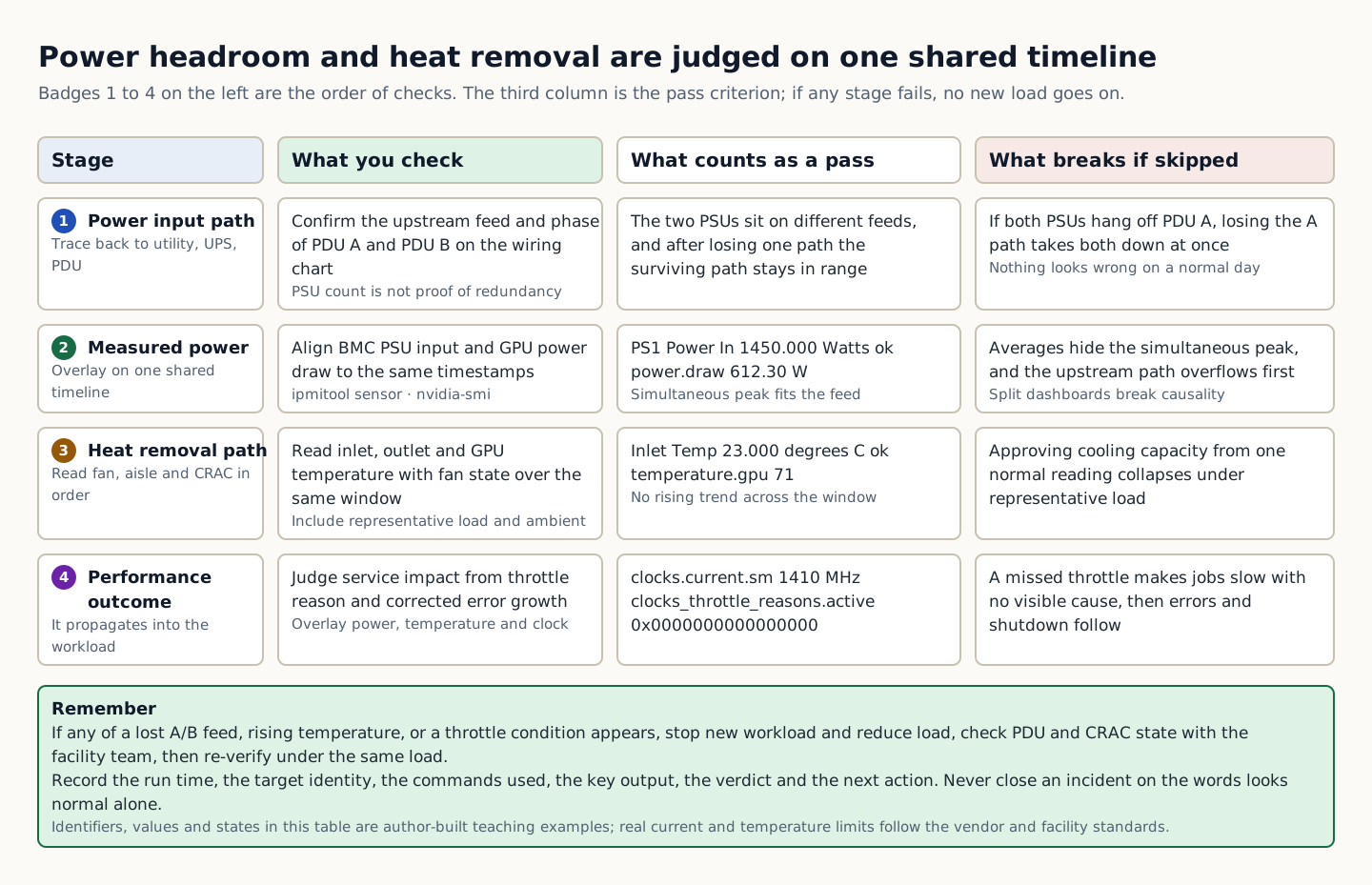
In the training example both PSUs were connected to PDU A and nothing seemed wrong in normal operation. If the A path is lost both PSUs go down together, so you cannot approve redundancy by counting PSUs. You must confirm that the load, split across two paths under normal conditions, stays within the allowed range after one path is lost. Actual allowed current and temperature follow the vendor and facility standards; do not apply the example temperature to all equipment.

A verdict table that splits four stages (power input path, measured power, heat removal path, and performance outcome) into what to check, the pass criterion, and what breaks if the stage is skipped
How to read the figure Badges 1 to 4 on the left give the order of checks, and each row is one stage: power input path, measured power, heat removal path, and performance result. The second column is what to check at that stage, the third is the state that counts as a pass along with training example values, and the fourth is what breaks if the stage is skipped. Row 1 checks whether the two PSUs are connected to different feeds, and confirms that if both are on PDU A, they go down together when the A path is lost. In rows 2 and 3, PS1 Power In 1450.000 Watts ok, power.draw 612.30 W, Inlet Temp 23.000 degrees C ok, and temperature.gpu 71 are training example values composed by the author; actual current and temperature limits follow the vendor and facility standards. Row 4 overlays clocks.current.sm 1410 MHz and clocks_throttle_reasons.active 0x0000000000000000 on the power and temperature from the same time. The green summary box at the bottom is the decision rule: if any of a lost A/B feed, rising temperature, or a throttle condition appears, stop new workloads and reduce the load. The table shows the order of checks and decision criteria; it does not depict actual wiring or time proportions. Source: composed by the author based on NVIDIA DCGM User Guide · NVIDIA System Management Interface.
Why does this happen?
Power reaches the components through the utility, UPS, PDU, rack PDU, and PSU, and the heat generated leaves through the fans, aisles, and CRAC units. If either side runs short of margin, the problem propagates to workloads as clock throttling, errors, or shutdowns.
When is it a problem?
If you see a lost A/B feed, rising temperature, or throttling, there are insufficient grounds to proceed.
Common beginner misconceptions
Do not approve cooling capacity based on a normal temperature at a single point in time. Look at a time window that includes representative load and outdoor and facility conditions.
How to verify it yourself
Check the upstream feeds and phases of PDU A and B on the cabling sheet. Align the BMC PSU input and the GPU power draw to the same time window.
To summarize this sectionYou succeed when you state in numbers the headroom on each A/B feed, the temperature change, the clock impact, and the threshold for stopping new load.
Conceptual explanation 02

CDU placement determines the failure domain and the maintenance unit

A CDU (Coolant Distribution Unit) sits between the FWS (Facility Water System) and the TCS (Technology Cooling System). It uses a plate heat exchanger to keep the two water loops from mixing, circulates technology cooling water with pumps, and establishes temperature, pressure, flow, and water-quality boundaries. In high-density GPU racks, where liquid replaces the air-cooling path covered in the previous unit (fans, aisles, CRAC), this device sits at the center of the cooling capacity path.

A CDU does the same job wherever it is installed. What differs is where the device sits and how many racks it serves. In the field, the two types are called the In-Rack CDU (built into the rack) and the In-Row CDU (installed in the row). An In-Rack CDU fits into 4U inside a rack and serves that one rack, while an In-Row CDU is a floor-standing cabinet placed beside or at the end of a rack row and serves multiple racks. Facility-scale CDUs that serve several rows at once also exist, but these two are what a new hire must distinguish first.

With In-Rack, facility water piping reaches the CDU inside the rack and the equipment coolant loop ends within that rack, so the volume stays at tens of liters and one CDU failure stays confined to 1 rack. With In-Row, facility water comes only as far as the floor-standing CDU while the equipment coolant supply and return headers run the length of the row, so the volume is hundreds of liters or more and one CDU failure affects every rack in that row. That is why In-Row design does not stop at N+1 pumps; it also provides redundancy for the CDU itself or UPS-backed power.

Read vendor capacity figures together with the approach temperature (ATD) condition. The approach is the difference between the facility water supply temperature and the technology cooling supply temperature; the smaller it is, the colder the coolant you can produce from the same facility water. 2 MW at 3 °C and 2 MW at 5 °C produce different coolant temperatures from the same facility water, so a kW figure without an approach condition cannot yet be compared.

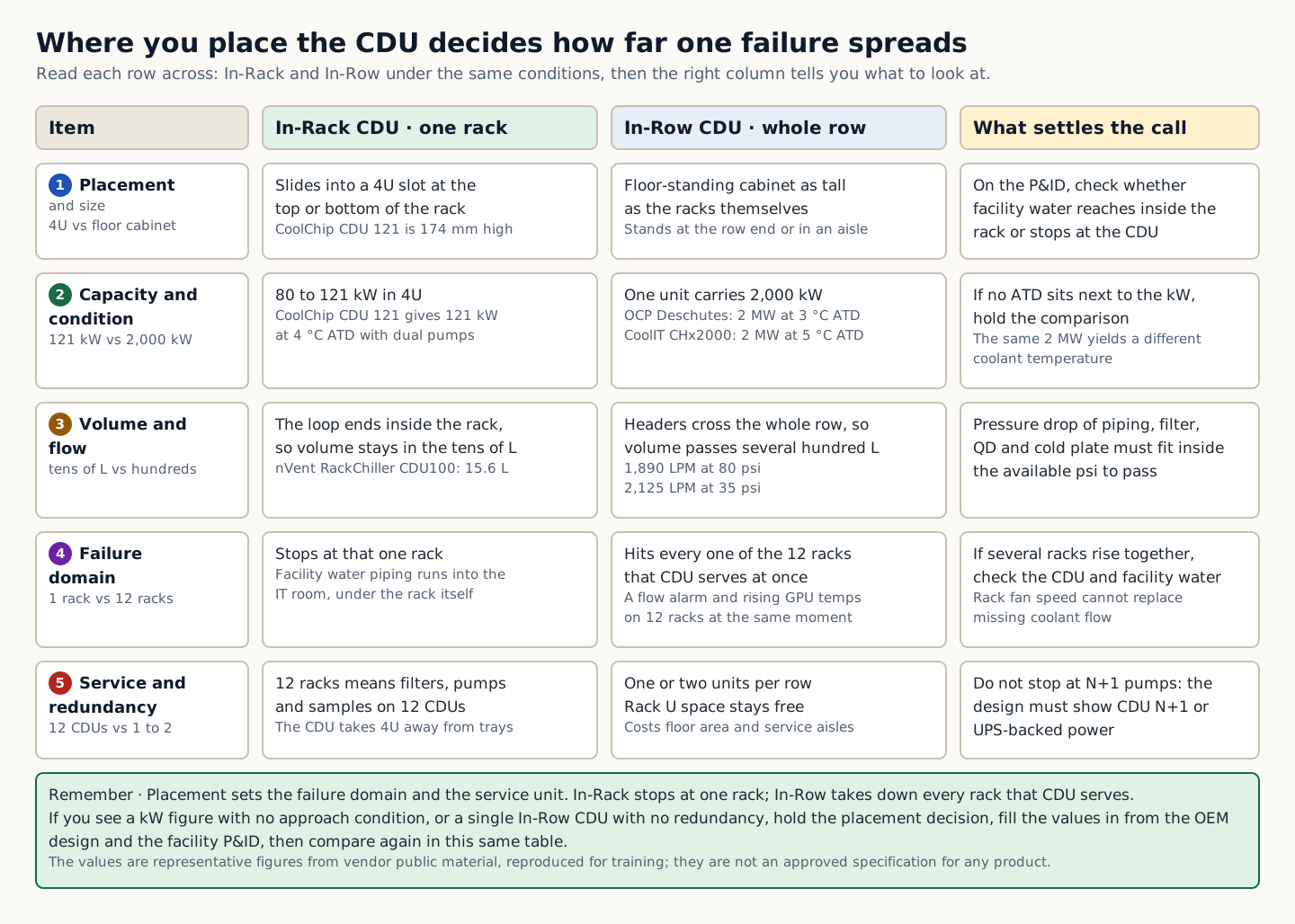
In the training example, 12 racks in one row shared a single In-Row CDU, and along with a CDU flow alarm, the GPU temperatures in all 12 racks rose at the same time. With an In-Rack CDU in each rack, the symptom would have been confined to one rack; instead, it spread across the whole row, and raising rack fan speed cannot make up for insufficient flow in the liquid loop. Recording at design time that placement determines the failure domain (the scope of common failure) speeds up the first judgment during operations.

A table comparing In-Rack CDU and In-Row CDU across placement and size, capacity and approach condition, volume and flow, failure domain, and service and redundancy, with what to look at to decide each item
How to read the figure CDU placement determines the failure domain and the unit of maintenance. Using the item column on the left as the reference, read the In-Rack CDU column and the In-Row CDU column side by side under the same conditions, and check the rightmost column for what to look at to reach a verdict. Badges 1 to 5 run in the order placement and size, capacity and approach conditions, volume and flow, failure scope, and maintenance and redundancy. Read capacity together with the ATD condition next to the kW value; if the condition is missing, that kW value cannot yet be compared, so hold the comparison. The failure scope row shows the difference that In-Rack stops at one rack, while In-Row affects all 12 racks served by that CDU. This means that if temperatures rise across several racks together, check the CDU and facility water boundary first, and if only one rack heats up, narrow the scope to that rack's branch, QD, and filter. The green box at the bottom holds the decision rules. The capacities, dimensions, and flow rates in the table are representative values from official vendor sources reproduced for training, not approved specifications for any particular product. The figure does not depict the actual proportions of piping lengths or equipment sizes, and OEM design documents and the facility P&ID take precedence. Source: composed by the author based on Vertiv · Evaluating coolant distribution unit (CDU) architectures · Vertiv CoolChip CDU 70–2300 kW · Vertiv CoolChip CDU 121 In-Rack · CoolIT Systems Coolant Distribution Units, and others.
Why does this happen?
With In-Rack, facility water piping runs into the CDU inside the rack and the technology cooling loop ends within that rack, so the volume stays at a few tens of liters and the failure of one CDU stays within a single rack. With In-Row, facility water comes only as far as the floor-standing CDU while the technology cooling supply and return headers run across the entire row, so the volume reaches hundreds of liters or more and one CDU failure affects every rack in that row. That is why In-Row designs do not stop at N+1 pumps; they also include redundancy for the CDU itself or a UPS-backed feed.
When is it a problem?
If kW figures are compared without approach conditions, or a single In-Row CDU has no redundancy, do not use the placement decision or product comparison as valid design evidence.
Common beginner misconceptions
In-Rack is not automatically the safe choice just because a failure affects only one rack. Facility water piping enters the IT room and runs under the racks, so responsibility boundaries must be redrawn rack by rack, and the number of units to maintain grows with the number of racks. Conversely, In-Row has fewer units to manage, but one CDU is a single point of failure for the entire row, so N+1 pumps alone do not complete the redundancy.
How to verify it yourself
On the P&ID, check how far the facility water piping runs (into the rack / only to the CDU) and where the technology cooling loop ends (inside the rack / across the whole row). Check that the vendor specification lists the approach temperature condition, flow rate (LPM), available pressure (psi), and filter rating next to the capacity.
To summarize this sectionYou succeed when, for each of the two designs, you write down how far the facility water reaches, where the technology cooling loop ends, how many racks stop when one CDU stops, and how many CDUs must be managed, and when you place the vendor specifications in one table by approach condition, flow rate, pressure, redundancy unit, filtration, control protocol, and service access side.

CHAPTER 1 / 14

Start the checks at the power input

Do not guess the cause and start by changing settings. If you group the following evidence into records from the same time window, another operator can reproduce the boundary at which the expected state broke.

1. Check the upstream feed and phase of PDU A/B in the cabling table. 2. Align the BMC PSU input and the GPU power draw to the same time window. 3. Check the inlet, outlet and GPU temperatures together with the fan status. 4. Judge the service impact from the throttle reason and whether corrected errors increased.

CHAPTER 2 / 14

Fix the lab target for server load

Commands for reproducing the isolated environment · do not run them in the browser
ipmitool sensor | grep -Ei 'Inlet|Exhaust|PS[12].*Power|Fan'
nvidia-smi --query-gpu=timestamp,power.draw,temperature.gpu,clocks.sm,clocks_throttle_reasons.active --format=csv

CHAPTER 3 / 14

Distinguish the output of heat rejection from what it means

Expected output for training · not an actual measurement
Inlet Temp | 23.000 | degrees C | ok
PS1 Power In | 1450.000 | Watts | ok
timestamp, power.draw [W], temperature.gpu, clocks.current.sm [MHz], clocks_throttle_reasons.active
2026/08/31 10:15:00, 612.30 W, 71, 1410 MHz, 0x0000000000000000

CHAPTER 4 / 14

Make the go/stop decision on the performance results

CHAPTER 5 / 14

Re-verify recovery of power and cooling

In-Row CDU and In-Rack CDU: the maintenance unit set by the layout

CHAPTER 6 / 14

An In-Rack CDU's loop ends inside the rack

In this example, the In-Rack CDU fits into a 4U slot at the top or bottom of a 19-inch rack. Facility water enters the primary side of that 4U unit, takes heat from the equipment coolant in a plate heat exchanger, and returns. On the secondary side, equipment coolant passes through the rack manifold and the cold plates in each tray and returns within the same rack. Because the loop is short, the fluid volume is small, and filling, draining, and sampling are easy.

In exchange, facility water piping enters the room that houses the IT equipment, right up to the underside of the rack. The end of the facilities team's piping effectively sits inside IT team assets, so responsibility for valve operation, leak detection, and drainage must be reassigned rack by rack. Twenty racks mean twenty CDUs, so filter replacements, pump redundancy checks, and water samples all multiply twentyfold, and the 4U occupied by each CDU also reduces the number of trays.

Representative values from official sources are as follows. The Vertiv CoolChip CDU 121 delivers 121 kW at an approach of 4 °C in a unit 174 mm tall, with built-in dual pumps and a 50 µm filter. The CoolIT CHx80 delivers 80 kW in 4U with N+1 pumps and power supplies, and mounts at the top or bottom of the rack. The Motivair by Schneider Electric In-Rack CDU delivers up to 105 kW in 4U with dual circulation pumps. The nVent RackChiller CDU100 fits in 4U, with a secondary-side volume of 15.6 L and two pumps in an N+1 configuration.

CHAPTER 7 / 14

An In-Row CDU serves the whole row as a single loop

An In-Row CDU is a floor-standing cabinet the same height as a rack, placed at the end of a row, between rows, or in an aisle. Facility water comes only as far as this cabinet, and the secondary-side equipment coolant supply header runs above the row or under the floor past every rack before returning through the return header. Because one unit serves the whole row, there are only one or two units to manage and no rack space is used, but the headers, branches, and hoses form one large loop with a volume of hundreds of liters or more.

Because one CDU becomes a single point of failure for the entire row, N+1 pumps are not enough; make the CDU itself N+1 or feed it from a UPS. Project Deschutes, which Google contributed to OCP, uses this In-Row approach, and Google states that by making the pumps and heat exchange units redundant, it has maintained CDU availability of about 99.999 % since 2020. The OCP specification defines 2 MW at an approach of 3 °C and 500 GPM, and requires seal-less N+1 pumps, DI water or PG25 coolant, and dual AC feeds.

Representative values from official sources are as follows. The Vertiv CoolChip CDU 600, 1350, and 2300 deliver 600, 1,350, and 2,300 kW, respectively, at an approach of 4 °C. The CoolIT CHx2000 is rated at 2,000 kW at an approach of 5 °C, with 2,125 LPM at 35 psi, and a single unit is stated to serve 12 GB300 NVL72 racks. The Boyd ROL4000 and the nVent Project Deschutes Open CDU are rated at 2 MW at an approach of 3 °C, with 80 psi of available pressure, seal-less N+1 pumps, and a 0.2 µm side-stream filter. The STULZ CyberCool CMU is rated at 345–1,380 kW with 32 °C facility water and 36 °C equipment coolant.

CHAPTER 8 / 14

Compare the two structures on the same items

Form factor and location:: In-Rack units are built into a 4U slot at the top or bottom of the rack; In-Row units are floor-standing cabinets as tall as the racks, placed at the end of a row, between rows, or in an aisle. Scope of one unit:: In-Rack serves one rack; In-Row serves anywhere from several racks to an entire row. At the 2 MW class, official material includes an example of one unit serving 12 GB300 NVL72 racks. Where facility water reaches:: With In-Rack, facility water enters the rack itself, so facility water piping runs inside the IT room; with In-Row, it reaches only the CDU, so only equipment coolant piping runs along the rack row. Technology cooling volume:: In-Rack holds a few tens of liters (for example, 15.6 L), which makes filling, draining, and sampling easy; In-Row puts all headers, branches, and hoses on one loop, reaching hundreds of liters or more. Impact when one CDU fails:: With In-Rack, only that one rack; with In-Row, every rack the CDU serves, so add CDU N+1 or a UPS as well. What needs maintenance and water quality management:: In-Rack means managing filters, pumps, and sampling on one CDU per rack; In-Row means one or two CDUs per row. Rack space:: With In-Rack, the CDU occupies 4U, reducing the number of trays; with In-Row, the rack is unaffected, but floor space and front and rear service aisles are required. Where each fits:: In-Rack suits a small number of racks, retrofits into rooms that remain partly air-cooled, and rapid rack-by-rack growth; In-Row suits new builds and large AI clusters where high-density racks arrive a full row at a time.

CHAPTER 9 / 14

kW figures without an approach temperature cannot be compared

A heat exchanger cannot make the two water temperatures exactly equal. That gap between the facility water supply temperature and the technology cooling supply temperature is the approach temperature; the smaller it is, the colder the coolant you can produce from the same facility water, and conversely the same coolant temperature can be produced from warmer facility water, which reduces the chiller load. That is why vendor datasheets always attach a condition, such as "○○ kW at ○ °C ATD".

Read a review in five steps. First, match the approach conditions stated next to the capacity. Second, check the flow rate (LPM) and available pressure (psi). The combined pressure loss of the piping, filters, manifold, QD, and cold plates must fit within this for minimum flow to reach the farthest rack. Third, check the unit of redundancy: N+1 pumps, redundancy that extends to the power feed, and whether the CDU itself can be deployed as N+1 are different things. Fourth, check whether the filtration (side-stream 0.2 µm, whether dual filters allow servicing) and control protocols (Modbus · BACnet · SNMP · Redfish) are compatible with your BMS and DCIM. Fifth, confirm the service access sides (front, rear, top) and the availability of local spares and service networks.

CHAPTER 10 / 14

CDU vendor review: what the official material confirms

Vertiv:: The In-Rack CoolChip CDU 121 (4U, 121 kW at 4 °C ATD, dual pumps, 50 µm filter), the In-Row and perimeter CoolChip CDU 600, 1350, and 2300 (600, 1,350, and 2,300 kW at 4 °C ATD, liquid-to-liquid), and the liquid-to-air CoolChip CDU 70 (70 kW) form one product family, and Vertiv's own technical documents summarize the pros and cons of In-Rack (1 rack affected), In-Row (several racks), and gallery (several rows). CoolIT Systems:: The range includes the In-Rack CHx80 (4U, 80 kW, N+1 pumps and power) and CHx200, plus the Row-based CHx2000 (2,000 kW at 5 °C ATD, 2,125 LPM at 35 psi, front and rear service, 12 racks of GB300 NVL72 per CDU). Capacity figures are stated together with ATD, flow rate, and pressure. Motivair by Schneider Electric:: The In-Rack CDU (4U, up to 105 kW, dual circulation pumps, mounted at the top or bottom of the rack) and the floor-standing MCDU-25 to MCDU-60 form one portfolio, and the MCDU-45 and 55 for utility corridor installation were announced on 2025-12-15. Since the 2025 acquisition by Schneider Electric, the company has emphasized integration with chiller plants. Boyd:: The In-Row liquid-to-liquid ROL4000 is rated at 2 MW at 3 °C ATD, with 80 psi available pressure, seal-less N+1 pumps, dual power feeds for each pump circuit, and a 0.2 µm side-stream filter. It is listed on the OCP Marketplace and references the fifth-generation Google Project Deschutes design. No In-Rack product could be confirmed in the official material. nVent:: The lineup includes the In-Rack RackChiller CDU100 (4U, 15.6 L on the secondary side, 2 pumps in N+1), the Row CDU RackChiller CDU800 (installed on a slab, on a raised floor, within a row, or in a separate mechanical room), and the Project Deschutes Open CDU (2 MW at 3 °C ATD, 1,890 LPM, 80 psi, N+1 seal-less pumps, 0.2 µm filter). nVent defines the role of the CDU as FWS isolation and limits on TCS temperature, dew point, flow rate, water quality, and pressure, and presents the ASHRAE S30 to S50 class table alongside. STULZ:: The In-Row class CyberCool CMU is specified at 345 to 1,380 kW and rated for 32 °C facility water supply and 36 °C equipment coolant supply, with optional redundant controllers, power, and pumps, and Modbus, BACnet, and SNMP control; it integrates the heat exchanger, pumps, valves, and controller in one cabinet. No In-Rack product could be confirmed in the official materials. OCP Project Deschutes (specification):: This is not a product but an open specification contributed by Google. It defines a 5th-generation In-Row CDU at 2 MW, approach 3 °C at 500 GPM, N+1 seal-less pumps, DI water or PG25, dual AC feeds, and a width of about 65 inches, and Boyd, nVent, Vertiv, and STULZ have listed products built to it on the OCP Marketplace.

The list above is neither a complete vendor list nor a purchase recommendation. An item marked as not confirmed does not mean the item does not exist, only that it could not be found in the official material. Manufacturer names are a starting point for asking the five questions above, not the answer.

CHAPTER 11 / 14

Criteria for choosing by site conditions

In-Row requires an equipment coolant header for each rack row, so the floor and ceiling piping routes, the CDU footprint and front and rear service space, and power feed redundancy must be settled early in the design. In-Rack, conversely, needs a facility water branch, isolation valves, and a leak tray at every rack. Either way, the required flow rate and pressure loss budget are fixed by the OEM design documents; the layout choice does not do that calculation for you.

There are four decision criteria. If you will keep adding high-density racks row by row and do not want more facility water connection points, choose In-Row; if you are starting liquid cooling with only a few racks, or maintenance outages must be limited to one rack, choose In-Rack. If you want to devote as much rack U space as possible to IT equipment, choose In-Row; if each rack has a different GPU configuration and heat load, and racks must not be pulled toward each other's operating point, choose In-Rack. Either way, operators read the same values; only the scope those values represent differs.

CHAPTER 12 / 14

Fix the order of checks

Before choosing a placement or comparing products, record the following items in the same design document. If even one is unconfirmed, do not guess the numbers; confirm them with the OEM or facility staff.

1. On the P&ID, check how far the facility water piping reaches (into the rack / up to the CDU) and where the equipment coolant loop ends (inside the rack / across the whole row). 2. Check how many racks are affected when one CDU stops, and whether the design document includes redundancy that narrows that scope (pump N+1, CDU N+1, UPS). 3. Check that the vendor specification lists the approach temperature condition, flow rate (LPM), available pressure (psi), and filter grade next to the capacity. 4. Count how many CDUs require maintenance items such as filters, pumps, and water-quality samples, and plan the maintenance interval to match the number of racks.

CHAPTER 13 / 14

A lab in reading candidate specifications under the same conditions

Commands for reproducing the isolated environment · do not run them in the browser
cat cdu-candidates.csv
awk -F, 'NR==1 || $3=="in-row"' cdu-candidates.csv
Expected output for training · not an actual measurement
vendor,model,type,atd_c,capacity_kw,flow_lpm,available_psi,pump_redundancy,secondary_volume_l,racks_served
training-a,rack-4u,in-rack,4,121,,,N+1,15.6,1
training-b,row-2mw,in-row,3,2000,1890,80,N+1,,12
training-c,row-2mw,in-row,5,2000,2125,35,N+1,,12
vendor,model,type,atd_c,capacity_kw,flow_lpm,available_psi,pump_redundancy,secondary_volume_l,racks_served
training-b,row-2mw,in-row,3,2000,1890,80,N+1,,12
training-c,row-2mw,in-row,5,2000,2125,35,N+1,,12

CHAPTER 14 / 14

Hold the placement decision if the specification or redundancy is lacking

CONCRETE CASES

Using the provided sensor snapshot, judge how power headroom and cooling anomalies affected the GPU clock.

Viewing power and cooling only on separate dashboards misses cause and effect at the same moment. Overlay GPU power, temperature, and clock, the BMC inlet temperature, and PDU phase current on the same time axis.

Wrong responses and boundaries to check

Do not approve cooling capacity based on a normal temperature at a single point in time. Look at a time window that includes representative load and outdoor and facility conditions. In-Rack is not automatically the safe choice just because a failure affects only one rack. Facility water piping now runs into the IT room and under the rack, so the responsibility boundary has to be redrawn per rack, and the number of maintenance targets grows with the number of racks. In-Row, by contrast, has fewer things to manage, but a single CDU is a single point of failure for the whole row, so N+1 pumps alone do not complete its redundancy.

If the temperature keeps rising or one feed disappears, stop new workloads and reduce the load. Check the PDU and CRAC status with the facilities owner, then re-verify under the same load. After recovery, measure again with the same commands and the same success criteria. Do not close an incident just because things appear normal. If a design review shows a capacity without its approach condition, a specification without flow rate and available pressure, or an In-Row layout with no CDU redundancy or UPS feed plan, hold the placement decision, fill in the values from the OEM design document and the facility P&ID, and compare again in the same table. On an installed site, if the temperature of several racks rises together, first check the CDU serving that row and the facility water boundary; if only one rack rises, narrow the scope to that rack's branch, QD, and filter. After recovery, compare again using the same table and the same success criteria. Do not approve a placement based on a vendor name or a single kW figure.

INTERACTIVE LAB 1 / 2

Lab 1 · Find the basis for a verdict in the output

Enter values in the browser and check the execution results and the failure and recovery paths. No commands are ever sent to real equipment or the NAS.

Lab scenario:: Using the provided sensor snapshot, judge the power headroom and the effect of the cooling anomaly on the GPU clock. Instructions:: In the browser, read the training output below and write a verdict. Do not send the commands to real equipment. To reproduce the commands separately, prepare an approved isolated environment with the relevant tools and example files. Save the entire output, and if you see loss of an A/B feed, a temperature rise, or throttling, do not move on to the next change. Lab scenario:: Read the training fixture of candidate CDU specifications and the 12-rack row layout, align the approach conditions, then write a placement verdict choosing In-Rack or In-Row, with your reasoning. Instructions:: In the browser, read the training fixture below and write a verdict. Do not send commands to real equipment or to a CDU controller. The column names are vendor, model, type, atd_c (approach °C), capacity_kw, flow_lpm, available_psi, pump_redundancy, secondary_volume_l, and racks_served. The values are representative figures from official manufacturer documentation, normalized for training.

Inlet Temp | 23.000 | degrees C | ok
PS1 Power In | 1450.000 | Watts | ok
timestamp, power.draw [W], temperature.gpu, clocks.current.sm [MHz], clocks_throttle_reasons.active
2026/08/31 10:15:00, 612.30 W, 71, 1410 MHz, 0x0000000000000000

The point is not to memorize the values themselves but to confirm that power, temperature, and clock are within the allowed range at the same moment and that no throttle reason is present. The values shown are reproduced examples for training, not measurements taken on real equipment. Identifiers and values can differ by device, driver, and cluster.

vendor,model,type,atd_c,capacity_kw,flow_lpm,available_psi,pump_redundancy,secondary_volume_l,racks_served
training-a,rack-4u,in-rack,4,121,,,N+1,15.6,1
training-b,row-2mw,in-row,3,2000,1890,80,N+1,,12
training-c,row-2mw,in-row,5,2000,2125,35,N+1,,12
vendor,model,type,atd_c,capacity_kw,flow_lpm,available_psi,pump_redundancy,secondary_volume_l,racks_served
training-b,row-2mw,in-row,3,2000,1890,80,N+1,,12
training-c,row-2mw,in-row,5,2000,2125,35,N+1,,12

This output is a training fixture, not the approved specification of any particular product. Rather than memorizing the values, read the following from it: the same 2,000 kW yields different coolant temperatures from the same facility water because atd_c is 3 in one case and 5 in the other; an In-Row candidate with racks_served of 12 makes one CDU the failure domain for 12 racks, so pump_redundancy N+1 alone does not complete the redundancy; and the In-Rack candidate has a small secondary_volume_l of 15.6, but 12 racks mean 12 CDUs to maintain.

INTERACTIVE LAB 2 / 2

Lab 2 · Plan for stopping and recovery

Enter values in the browser and check the execution results and the failure and recovery paths. No commands are ever sent to real equipment or the NAS.

Do not approve cooling capacity based on a normal temperature at a single point in time. Look at a time window that includes representative load and outdoor and facility conditions. In-Rack is not automatically the safe choice just because a failure affects only one rack. Facility water piping now runs into the IT room and under the rack, so the responsibility boundary has to be redrawn per rack, and the number of maintenance targets grows with the number of racks. In-Row, by contrast, has fewer things to manage, but a single CDU is a single point of failure for the whole row, so N+1 pumps alone do not complete its redundancy.

KEY TERMS

Key terms in this unit

Failure domain
The set of targets that a single power, cooling, or network failure can affect at the same time.
CDU (Coolant Distribution Unit)
A device that uses a plate heat exchanger to keep facility water and technology cooling water separate, circulates the technology cooling water with pumps, and establishes temperature, pressure, flow, and water-quality boundaries.
In-Rack CDU (rack-mounted CDU)
This is a CDU that fits into 4U of space at the top or bottom of a 19-inch rack and serves that one rack only. Facility water comes into the rack, and the equipment coolant loop ends inside the rack.
In-Row CDU (row-based CDU)
A floor-standing cabinet CDU placed beside or at the end of a rack row, with one unit serving several racks or an entire row. Facility water runs only as far as the CDU, and the equipment coolant header runs along the whole row.
approach temperature (ATD)
The difference between the supply temperatures on the two sides of the heat exchanger, that is, between the facility water supply temperature and the technology cooling supply temperature. A vendor capacity figure can be compared only when it is stated together with this condition.

UNIT WORKBOOK

Exercises and worksheets for applying concepts to new situations

Start by checking basic principles, then expand to practical workplace decisions. After submitting an answer, you can see why every option is correct or incorrect, not just the correct answer.

Document the stop conditions and recovery evidence for power and cooling in a work record.

PERSONAL WORKSHEET

A learning worksheet you adapt to your own environment

Your input remains only on the current browser screen and is not stored or transmitted externally. Use categories and pseudonyms instead of actual sensitive information.

OFFICIAL SOURCES

Verify against official sources

Reviewed against official documentation and training output. Commands and performance tests on real hardware are unconfirmed.

docs.nvidia.comNVIDIA DCGM User Guide2026-09-01 Review ↗docs.nvidia.comNVIDIA System Management Interface2026-09-01 Review ↗www.vertiv.comVertiv · Evaluating coolant distribution unit (CDU) architectures2026-09-02 Review ↗www.vertiv.comVertiv CoolChip CDU 70–2300 kW2026-09-02 Review ↗www.vertiv.comVertiv CoolChip CDU 121 In-Rack2026-09-02 Review ↗www.coolitsystems.comCoolIT Systems Coolant Distribution Units2026-09-02 Review ↗www.coolitsystems.comCoolIT Systems CHx2000 Row-based CDU2026-09-02 Review ↗www.coolitsystems.comCoolIT Systems CHx80 Rack CDU2026-09-02 Review ↗www.motivaircorp.comMotivair by Schneider Electric In-Rack Coolant Distribution Unit2026-09-02 Review ↗www.motivaircorp.comMotivair by Schneider Electric · New range of CDUs (MCDU-45·55)2026-09-02 Review ↗www.boydcorp.comBoyd ROL4000 2 MW In-Row CDU2026-09-02 Review ↗www.nvent.comnVent Coolant Distribution Units — RackChiller CDU100·CDU8002026-09-02 Review ↗www.opencompute.orgOCP Marketplace · nVent Project Deschutes Open CDU2026-09-02 Review ↗www.stulz.comSTULZ CyberCool CMU2026-09-02 Review ↗www.opencompute.orgOCP Project Deschutes 2 MW CDU Specification (2025-09-05)2026-09-02 Review ↗cloud.google.comGoogle Cloud Blog · Enabling 1 MW IT racks and liquid cooling at OCP EMEA Summit2026-09-02 Review ↗

CORE UNIT 4 / 4

The full path to the service

Draw the dependencies and failure domains that run from the user request down to the facility.

Difficulty
Intermediate
Structure
Lessons 5 · Labs 2 · Assessment

Diagrams and tables: composed by the author using each lesson's official primary sources. Find the originals and review dates at the end of that lesson.

PREREQUISITE CHECK

Three things to check before reading

This is not a test of memorized answers. Think about each question first, then open the explanation to review the foundational concepts used in this course.

1Does this unit send commands to real equipment?

No. Read the training output in the browser and make the judgment there. Any separate reproduction is done only in an approved isolated environment.

2What permissions and environment must you confirm before the lab?

No facility changes · read-only BMC account. Documentation management network 192.0.2.0/24.

3What evidence did you record in the previous unit, "Power and cooling"?

You succeed when you state in numbers the headroom on each A/B feed, the temperature change, the clock impact, and the threshold for stopping new load.

TEXTBOOK GUIDE

Main text that covers each concept from its background to the criteria for judging it

We explain the material section by section so readers new to IT can connect causes and effects without memorizing terms.

  1. Explain the components and failure boundaries of the full path to the service using a diagram.
  2. Judge the state of the full path to the service from command output and observed values.
  3. Document the stop conditions and recovery evidence for the full path to the service in a work record.
The full path to the service Lab environment and safety boundaries
HardwareRack diagram · PDU A/B · BMC sensor fixture
SoftwareUbuntu 24.04 LTS·ipmitool 1.8.x
Required permissionsNo facility changes · read-only BMC account
NetworkingDocumentation-range management network 192.0.2.0/24

Reviewed against official documentation and training output. Commands and performance tests on real hardware are unconfirmed.

Applies to version: Ubuntu Server 24.04 LTS · ipmitool 1.8.x · Manuscript review date: 2026-09-01

CONCEPT FLOW

How the chapters connect

The chapters are not isolated short answers to memorize. Follow them from left to right to see how each chapter's concepts support the next decision.

  1. 1.Start the checks from the user request
  2. 2.Pins down the lab target for the workload
  3. 3.Distinguish the output of the resource path from what it means
  4. 4.Make the go/stop decision on the facility foundation
  5. 5.Re-verify recovery of the full path to the service
The full path to the service: the overall map. If you lose track while reading the detailed explanations and chapters below, return to this sequence.

CONTROLLED EXPLANATION

Follow the evidence to check, one step at a time

Current explanation · 1/5 · Start the checks from the user request

Up next: Pins down the lab target for the workload

  1. Start the checks from the user request

    Do not guess the cause and start by changing settings. If you group the following evidence into records from the same time window, another operator can reproduce the boundary at which the expected state broke.

  2. Pins down the lab target for the workload

    Lab scenario:: Using the given service inventory, map the dependencies of a single request and find three common points of failure. Instructions:: In the browser, read the training output below and write a verdict. Do not send the commands to real equipment. To reproduce the commands separately, prepare an approved isolated environment with the relevant tools and example files. Save the entire output, and if a dependency has no owner or shares a common failure domain, do not move on to the next change.

  3. Distinguish the output of the resource path from what it means

    The point is not to memorize the values themselves but to confirm that you can trace which node and network path the replica serving the request sits on. The values shown are reproduced examples for training, not measurements taken on real equipment. Identifiers and values can differ by device, driver, and cluster.

  4. Make the go/stop decision on the facility foundation

    The task is complete when you present a map that runs from the user symptom through at least eight dependencies to the facility, with the owner and verification command for each. Record the execution time, target identity, commands used, key output, verdict, and next action together in the result.

  5. Re-verify recovery of the full path to the service

    Classify any boundary without an owner or a verification method as not operationally ready. Before release, add observability signals and an escalation path, and use fault injection to confirm that recovery follows the map. After recovery, measure again with the same commands and the same success criteria. Do not close an incident just because things appear normal.

Conceptual explanation 01

Trace from the user SLO down to the facility failure domain

Dependency: a lower-level service or resource that a higher-level function needs in order to work.

An AI service does not exist as an API alone. DNS, the gateway, the scheduler, the model runtime, the GPU, the fabric, storage, and the power and cooling beneath them form one continuous dependency path.

Each layer must have an identity, a healthy signal, an owner, a timeout, and a fallback. If two components share the same rack, PDU, or switch, they have only one real failure domain even if they look logically redundant.

The value of an architecture diagram is not in drawing many boxes. It must show which evidence goes to which owner when a request fails, and which shared boundaries to rule out first.

In the training example two API replicas sit on different nodes but use the same DNS resolver and object gateway. Even with both nodes Ready, a resolver failure can make new model downloads fail. Correlating the time of request failures with the times of name resolution and artifact lookups lets you judge that replacing a GPU is not the first step. Record the replica count and the shared dependencies together in the diagram.

A table listing the identifiers, healthy signals, and failure symptoms of six layers, from the user SLO through DNS and gateway, workload replica, GPU node, and storage artifact down to fabric, rack, and PDU
How to read the figure Follow a single request from the user SLO down to the facility failure domain. Read the layers in the table from top to bottom, and within each row look at how that layer is identified, what indicates a healthy state, and what symptom appears when it breaks. Badges 1 to 6 run in the order user SLO, DNS and gateway, workload replica, GPU node, storage artifact, and fabric · rack · PDU, and the left cell also names the owner of each layer. First find the symptom you are seeing in the symptom column, then group that row's identifier and healthy signal with records from the same time window to determine at which boundary the expected state broke. Row 3 means two Pods with different names can be on the same node or rack. Rows 5 and 6 mean that if two replicas share the same gateway or the same rack, PDU, or switch, the logical redundancy loses its meaning, so rule out shared boundaries first and only then suspect the GPU. The green box at the bottom holds the decision rules: a boundary with no owner or no verification method is classified as not ready for operations. The identifiers, numbers, and states in the table are training examples composed by the author, and the figure does not depict physical cabling or time proportions. Source: composed by the author based on Kubernetes Liveness, Readiness and Startup Probes · OpenTelemetry Context Propagation.
Why does this happen?
Each layer needs an identity, a healthy signal, an owner, a timeout, and a fallback. If two components share the same rack, PDU, or switch, they may look logically redundant, but they actually form a single failure domain.
When is it a problem?
If you see ownerless dependencies or a shared failure domain, there are insufficient grounds to proceed.
Common beginner misconceptions
Different Pod names do not mean different failure domains. Check placement down to the node, rack, switch, and PDU.
How to verify it yourself
Link the user SLO to the request ID at the first entry point. Attach the deployment revision, node, GPU UUID, and model digest to the same request.
To summarize this sectionYou succeed when you present a map that runs from the user symptom through at least eight dependencies to the facility, together with owners and verification commands.

CHAPTER 1 / 5

Start the checks from the user request

Do not guess the cause and start by changing settings. If you group the following evidence into records from the same time window, another operator can reproduce the boundary at which the expected state broke.

1. Connect the user SLO to the request ID at the first entry point. 2. Link the deployment revision, node, GPU UUID, and model digest to the same request. 3. Trace the storage path and the fabric port down to the physical switch and rack. 4. Mark the owner, dashboard, runbook, and fallback for each boundary.

CHAPTER 2 / 5

Pins down the lab target for the workload

Commands for reproducing the isolated environment · do not run them in the browser
kubectl get pod -n inference -o wide
kubectl get pod -n inference -l app=model-api -o jsonpath='{range .items[*]}{.metadata.name}{"\t"}{.spec.nodeName}{"\t"}{.metadata.labels.revision}{"\n"}{end}'
traceroute -n 192.0.2.80

CHAPTER 3 / 5

Distinguish the output of the resource path from what it means

Expected output for training · not an actual measurement
model-api-r7-abc  gpu-node-03  r7
model-api-r7-def  gpu-node-04  r7
traceroute to 192.0.2.80 ... 192.0.2.1 ... 192.0.2.80

CHAPTER 4 / 5

Make the go/stop decision on the facility foundation

CHAPTER 5 / 5

Re-verify recovery of the full path to the service

CONCRETE CASES

Using the given service inventory, map the dependencies of a single request and find three common points of failure.

The value of an architecture diagram is not in drawing many boxes. It must show which evidence goes to which owner when a request fails, and which shared boundaries to rule out first.

Wrong responses and boundaries to check

Different Pod names do not mean different failure domains. Check the placement down to the node, rack, switch and PDU.

Classify any boundary without an owner or a verification method as not operationally ready. Before release, add observability signals and an escalation path, and use fault injection to confirm that recovery follows the map. After recovery, measure again with the same commands and the same success criteria. Do not close an incident just because things appear normal.

INTERACTIVE LAB 1 / 2

Lab 1 · Find the basis for a verdict in the output

Enter values in the browser and check the execution results and the failure and recovery paths. No commands are ever sent to real equipment or the NAS.

Lab scenario:: Using the given service inventory, map the dependencies of a single request and find three common points of failure. Instructions:: In the browser, read the training output below and write a verdict. Do not send the commands to real equipment. To reproduce the commands separately, prepare an approved isolated environment with the relevant tools and example files. Save the entire output, and if a dependency has no owner or shares a common failure domain, do not move on to the next change.

model-api-r7-abc  gpu-node-03  r7
model-api-r7-def  gpu-node-04  r7
traceroute to 192.0.2.80 ... 192.0.2.1 ... 192.0.2.80

The point is not to memorize the values themselves but to confirm that you can trace which node and network path the replica serving the request sits on. The values shown are reproduced examples for training, not measurements taken on real equipment. Identifiers and values can differ by device, driver, and cluster.

INTERACTIVE LAB 2 / 2

Lab 2 · Plan for stopping and recovery

Enter values in the browser and check the execution results and the failure and recovery paths. No commands are ever sent to real equipment or the NAS.

Different Pod names do not mean different failure domains. Check the placement down to the node, rack, switch and PDU.

KEY TERMS

Key terms in this unit

Dependency
A lower-level service or resource that a higher-level function needs in order to work.

UNIT WORKBOOK

Exercises and worksheets for applying concepts to new situations

Start by checking basic principles, then expand to practical workplace decisions. After submitting an answer, you can see why every option is correct or incorrect, not just the correct answer.

Document the stop conditions and recovery evidence for the full path to the service in a work record.

PERSONAL WORKSHEET

A learning worksheet you adapt to your own environment

Your input remains only on the current browser screen and is not stored or transmitted externally. Use categories and pseudonyms instead of actual sensitive information.

OFFICIAL SOURCES

Verify against official sources

Reviewed against official documentation and training output. Commands and performance tests on real hardware are unconfirmed.

DECISION ACTIVITY

The current on PDU A in rack A reached the warning line, but the GPU nodes are healthy. Which action is correct?

First write down the evidence you need and the stop criteria, then choose a verdict.

Choose an answer

THREE-LEVEL ASSESSMENT

From basic principles to operational decisions

When you submit an answer you can see why every option is right or wrong.

Basic Question 1

What must differ for a server with dual power supplies to be truly redundant?

Choose an answer
Apply Question 2

GPU temperatures rise together across 12 racks in the same row, and one In-Row CDU serving that row raised a flow alarm. What is the correct judgment?

Choose an answer
Capstone Question 3

Services in two racks went down at the same time. What is a good initial hypothesis?

Choose an answer

LEARNING RECORD

Have you reviewed the text, decision activities, and all explanations?

Completion status is stored only in this browser.